Tamara Alenezi · Structural LinkedIn

Penn State · Architectural Engineering · Structural Option

Tamara Alenezi

Structural engineer in training, designing how buildings carry load from the frame out to the façade.

Tamara is finishing her architectural engineering degree at Penn State, in the ABET-accredited structural option. She is trained in steel, concrete and timber design, indeterminate analysis, and wind and seismic loading, and works in analysis models (SAP2000, ETABS, RAM) as well as coordinated BIM documentation (Revit, AutoCAD). She is looking for an entry-level role designing building structures.

Elevation of a six-story building with wind pressure arrows increasing with height A B C V = 180 mph Exp. C · Risk Cat. III 6 @ 17′-4″ = 104′-0″ Curtain wall Punched windows Zone 5 C&C: 123.56 psf
Diagram: the capstone building's windward face. Velocity pressure goes up with height, and the edge zone suction controls the cladding design.
B.A.E.Architectural Engineering, Structural Option. Expected Dec. 2026
123.56 psfGoverning Zone 5 suction used to design three façade systems
0.52 inInterstory drift (h/400) each façade system was checked to accommodate
3Enclosure systems detailed from glass to slab: curtain wall, punched window, rainscreen
SheetS-01
Calculations · from coursework to capstone

How the numbers were made

Each topic below follows one part of the degree into the capstone calculations, step by step, with the actual inputs, equations and results from the thesis sheets. Open any card to see the full process.

SheetS-02
Senior capstone

Moving a classroom building to the hurricane coast

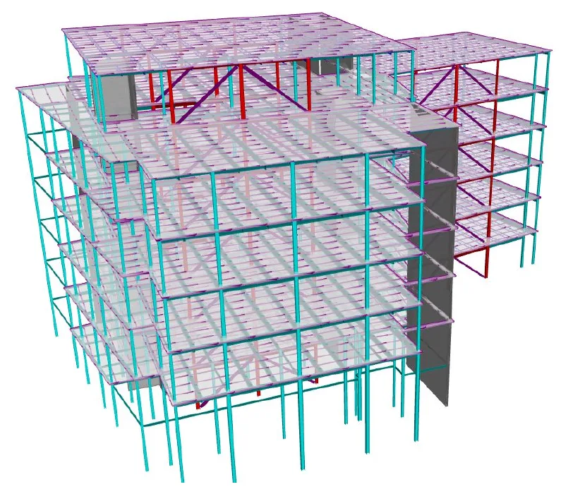
The structural team was given an existing general purpose classroom building and asked to redesign it for a new site in Boca Raton, Florida, with three added stories and an owner requirement to use mass timber. The move to the coast changes almost everything: much higher wind speeds, a more humid climate, more thermal demand, and the Florida Building Code.

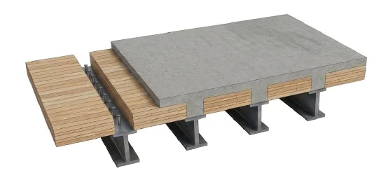
The team replaced the original composite steel deck with cross-laminated timber (CLT) panels on steel framing. They also redesigned the foundations and rebuilt the enclosure for coastal wind. Tamara's part was the enclosure: choosing the façade systems, deriving their components & cladding wind demands, detailing every connection back to the structure, and checking that they can take the building's drift.

Project
General Purpose Classroom Building
Site
Boca Raton, FL · Risk Category III
Firm
Anchor Point Engineering (student team)
Structural
Tamara Alenezi · Nicholas DeMarco · Kevin Regep · Kohshin Noma
Other disciplines
Lighting/Electrical · Mechanical · Construction
Her sheets
S.3.1–S.3.3 enclosure connections · AP.1–AP.6 C&C, assemblies, drift, hand calcs
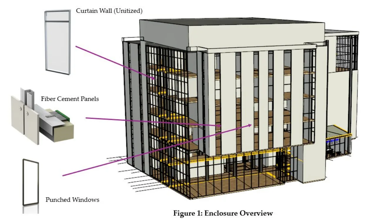
3D model of the six-story classroom building with callouts to the unitized curtain wall, fiber cement panels, and punched windows
AP.1 · Enclosure overview. Where the three systems sit on the building: the unitized curtain wall, the fiber cement rainscreen and the punched windows.
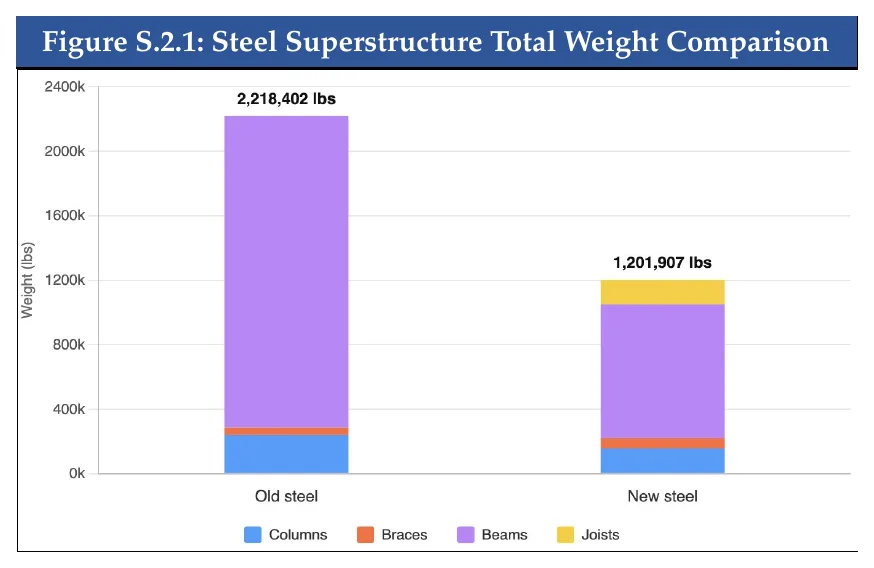
45.8%

Less steel by weight: 2,218,402 lb → 1,201,907 lb, after the lighter CLT deck let the frame be resized.

Team result · sheet S.2
≈ 40%

Lower embodied carbon in the gravity superstructure, beating the project's 30% target.

Team result · sheet S.2
65.6%

Vibration utilization of the CLT floor (10.75 ft max span vs. 16.38 ft allowable), so walking vibration doesn't govern.

Team result · sheet S.4
SheetS-03
The drawing set

Every sheet of the thesis

All 17 structural sheets from the Anchor Point Engineering capstone, in order. Use the arrows, the sheet tabs or your keyboard's arrow keys to move through them. Click a sheet to open it full size.

Thesis sheet S.1: Code, Standards & Resources
S.1Code, Standards & ResourcesK. Noma
Thesis sheet S.1: Loading & Site Conditions
S.1Loading & Site ConditionsK. Noma
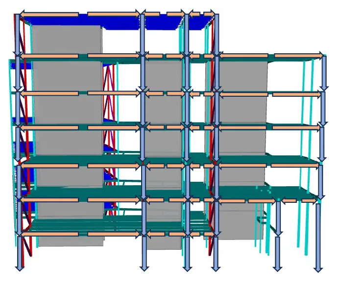
Thesis sheet S.2: Structural Framing & Weight Comparisons
S.2Structural Framing & Weight ComparisonsK. Noma
Thesis sheet S.3: Gravity Floor System Selection & Analysis
S.3Gravity Floor System Selection & AnalysisK. Noma
Thesis sheet S.4: Vibration & Modelling Procedure
S.4Vibration & Modelling ProcedureK. Noma
Thesis sheet S.: Foundations & Façades: Codes and Processes
S.Foundations & Façades: Codes and ProcessesK. Regep
Thesis sheet S.3.1: Enclosure Connections: Fiber Cement
S.3.1Enclosure Connections: Fiber CementTamara Alenezi
Thesis sheet S.3.2: Enclosure Connections: Curtain Wall
S.3.2Enclosure Connections: Curtain WallTamara Alenezi
Thesis sheet S.3.3: Enclosure Connections: Punched Window
S.3.3Enclosure Connections: Punched WindowTamara Alenezi
Thesis sheet S.: Façades: Spandrel Torsion Design
S.Façades: Spandrel Torsion DesignK. Regep
Thesis sheet S.: Façades: GFRC Components & Cladding
S.Façades: GFRC Components & CladdingK. Regep
Thesis sheet AP.1: Final Enclosure System + C&C Summary
AP.1Final Enclosure System + C&C SummaryTamara Alenezi
Thesis sheet AP.2: Fiber Cement Enclosure Component
AP.2Fiber Cement Enclosure ComponentTamara Alenezi
Thesis sheet AP.3: Curtain Wall Enclosure Component
AP.3Curtain Wall Enclosure ComponentTamara Alenezi
Thesis sheet AP.4: Punched Window Enclosure Component
AP.4Punched Window Enclosure ComponentTamara Alenezi
Thesis sheet AP.5: Façade Drift Analysis
AP.5Façade Drift AnalysisTamara Alenezi
Thesis sheet AP.6: Hand Calculations: C&C and IGU Comparison
AP.6Hand Calculations: C&C and IGU ComparisonTamara Alenezi
01 / 17

Orange tabs are Tamara's sheets. The others were authored by her structural teammates, as marked in each sheet's title block.

SheetS-04
Her scope · enclosure & components and cladding

Designing the skin for 180 mph wind

Design basis

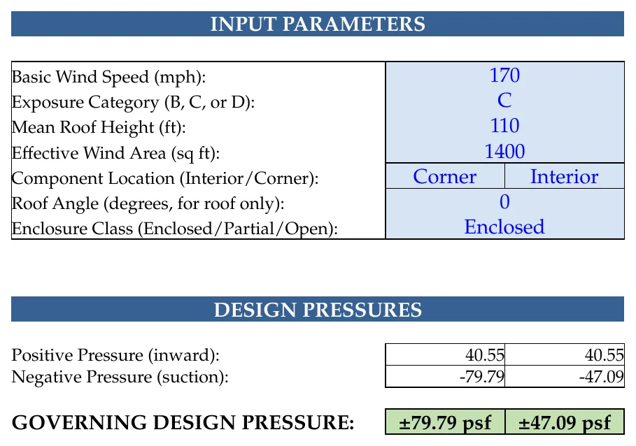
Each façade element was analyzed as its own component under ASCE 7-22 Chapter 30. The edge zone suction (Zone 5) was taken as the governing demand for every system.

CodesFBC 2023 · ASCE 7-22
Risk categoryIII
ExposureC
Basic wind speed, V180 mph
EnclosureEnclosed
Velocity pressure, qh89.54 psf
Internal pressure, GCpi±0.18
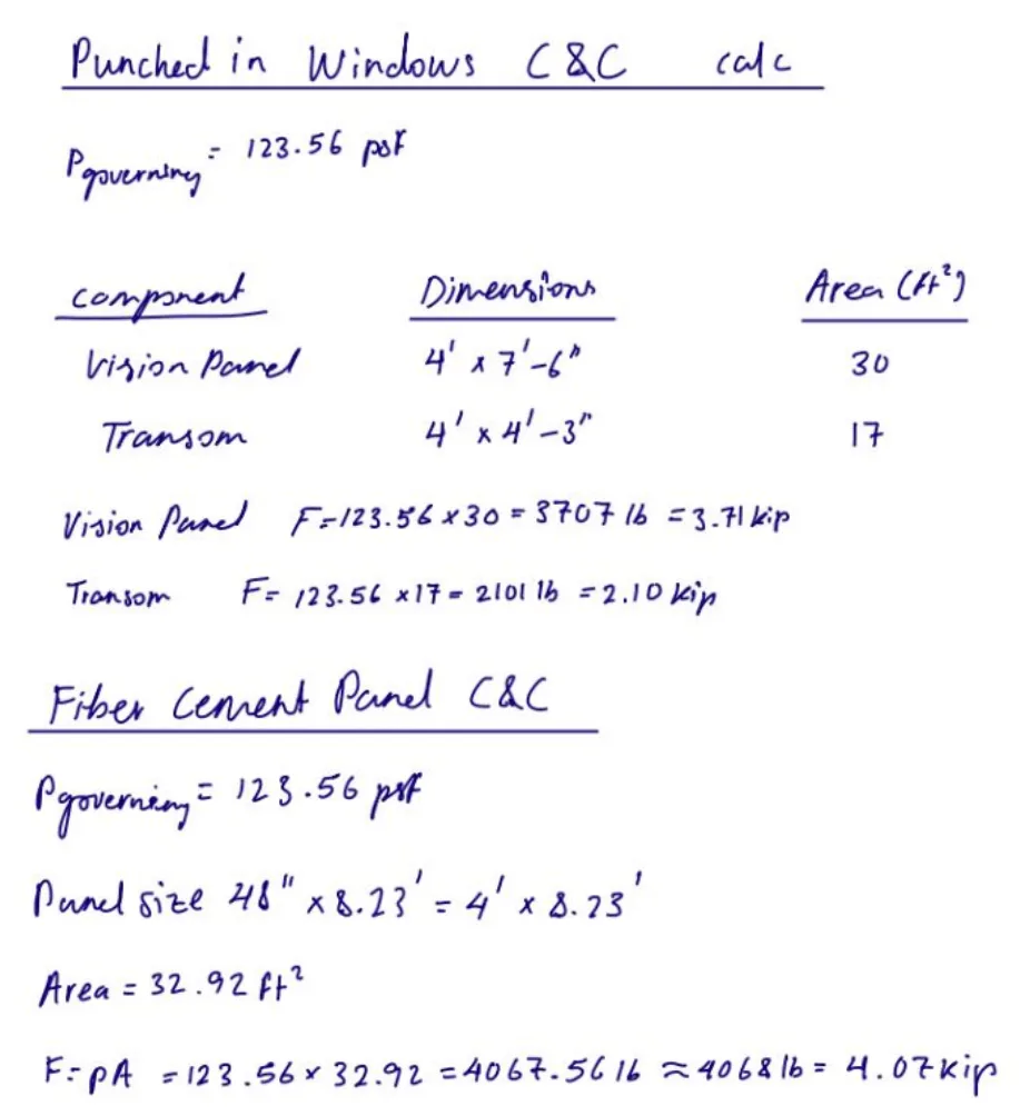
Governing Zone 5 suction123.56 psf

Procedure

  1. Site wind parametersBasic wind speed and exposure for a Risk Category III building, from the ASCE Hazard Tool.
  2. Velocity pressureqz = 0.00256 KzKztKdV², evaluated at mean roof height.
  3. Effective wind areaSet by the component's tributary area: panel, glazing unit or transom.
  4. Surface zoneWall zones 4 (field) and 5 (edge/corner). Zone 5 suction governs.
  5. External & internal coefficientsGCp for the zone and area, with GCpi = ±0.18 for an enclosed building.
  6. Net design pressure → forcesPressure × area gives the panel force, which is followed through every connection to the structure.
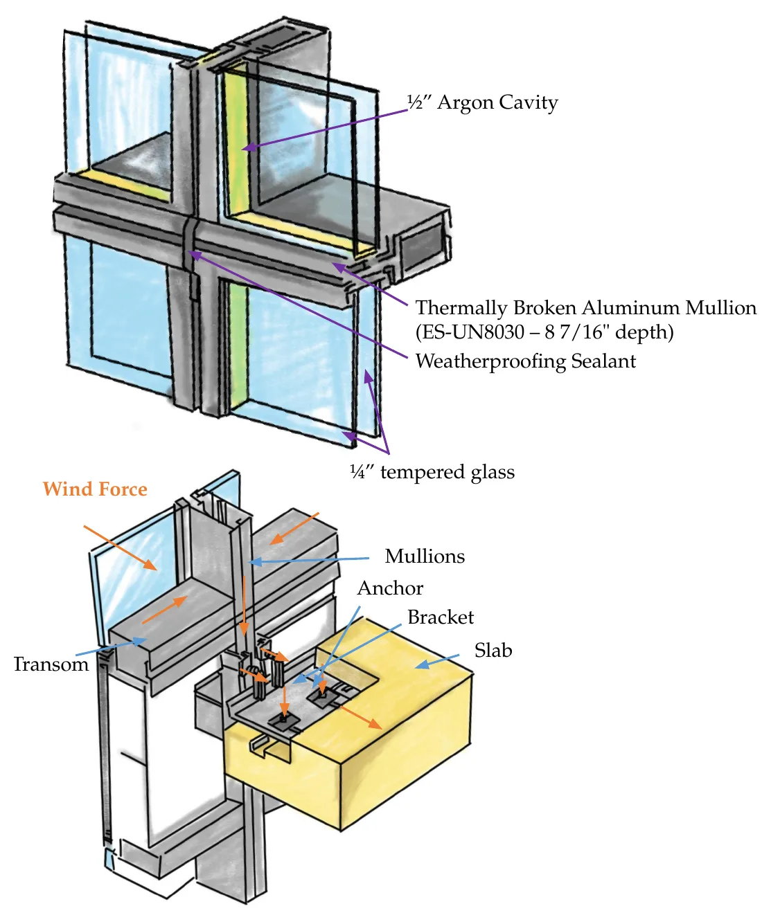
Hand-rendered axonometric of a unitized curtain wall: argon-filled double glazing in thermally broken aluminum mullions, and the anchor and bracket connection to the slab edge
S.3.2 · Fig. 1–2. Unitized curtain wall and the load path into the slab edge.
System 01 · Sheet S.3.2

Unitized curtain wall

ES-UN8030 captured system · two stacked units per floor

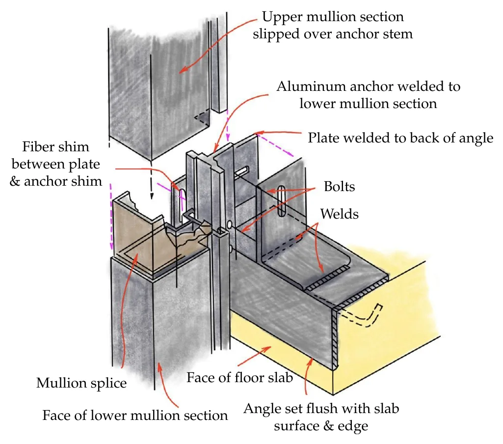
Factory-glazed units run floor to floor and hang off the slab edge. The upper connection is a sliding anchor: the upper mullion section slips over an anchor stem welded to the lower one. That lets each floor move relative to the next under interstory drift and thermal movement without loading the glass.

Unit size
60″ × 17′-4″
Upper unit
5′ × 11′ · 6.80 k
Lower unit
5′ × 6′-4″ · 3.91 k
Line load
294.61 plf
System depth
19.44 in
U-value
0.34

Load path

  • Glass
  • Frame
  • Anchor lugs
  • Brackets
  • Slab
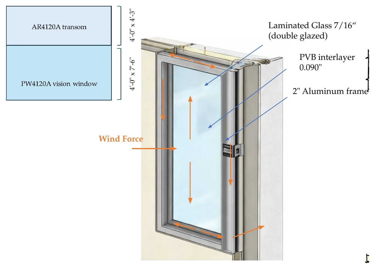
Punched window with laminated double glazing, showing wind force on the glass transferring to the aluminum frame and perimeter anchors
S.3.3 · Overview. Vision window and transom.
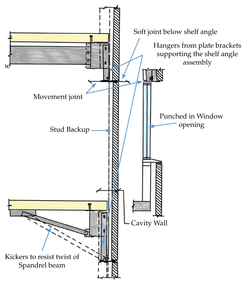
Wall section showing a hung shelf angle at the window head, movement joints, stud backup, and kickers resisting spandrel beam twist
S.3.3 · Section. Hung shelf angle per AISC DG 22.
System 02 · Sheet S.3.3

Punched windows

PGT-Sparta™ impact window · laminated 7/16″ glazing, 0.090″ PVB interlayer

A punched window doesn't go to the slab edge. It's a discrete unit anchored at its jambs, head and sill into the surrounding stud wall, so the wall is the load path. The head is detailed with a shelf angle hung from plate brackets, with a soft joint below it, following AISC Design Guide 22. Kickers back to the slab resist twist in the spandrel beam.

Vision
4′-0″ × 7′-6″
Vision force
3.71 kip
Transom
4′-0″ × 4′-3″
Transom force
2.10 kip
Line load
246.95 plf
Anchors
Jambs · head · sill

Load path

  • Glass
  • Frame
  • Anchors
  • Stud wall
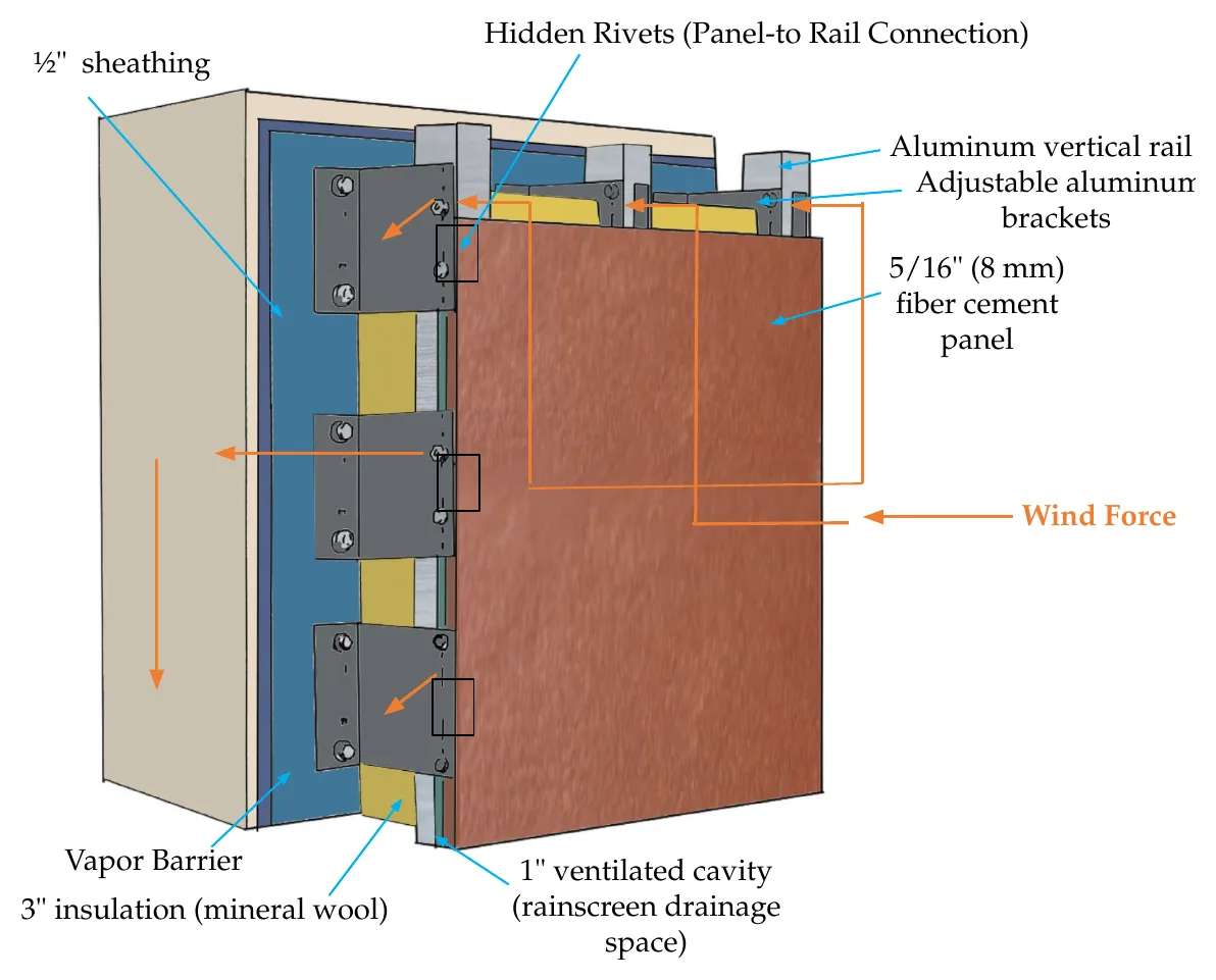
Exploded rainscreen assembly: fiber cement panel on hidden rivets, aluminum vertical rails, adjustable brackets, mineral wool insulation, vapor barrier and sheathing
S.3.1 · Fig. 1. Rainscreen assembly and load path.
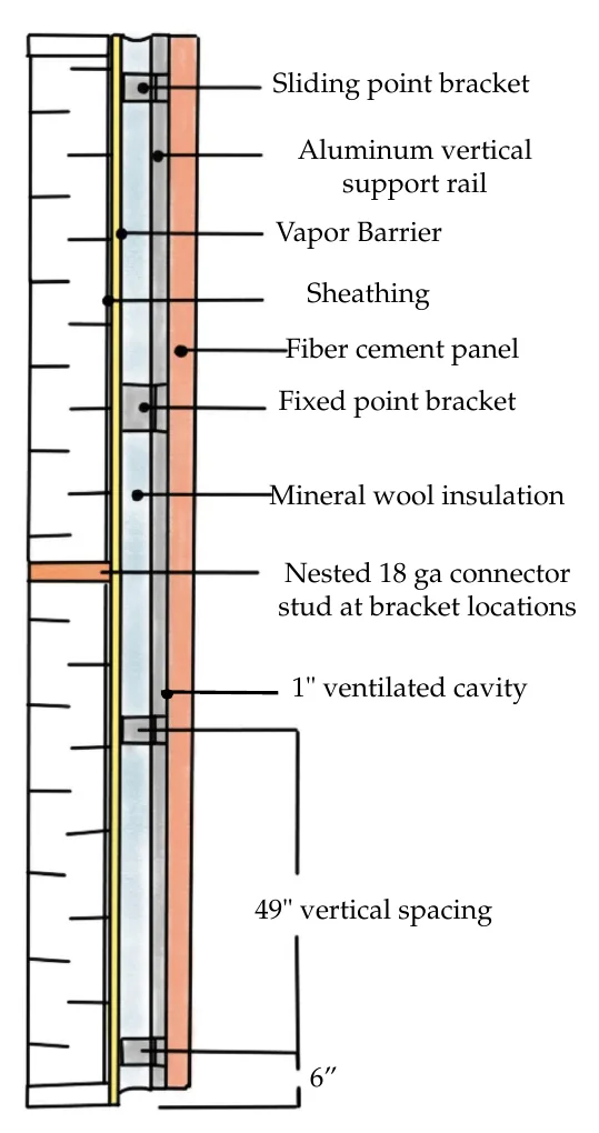
Section through the rainscreen showing fixed and sliding point brackets at 49 inch spacing
S.3.1 · Fig. 3. Fixed / sliding brackets, 49″ o.c.
System 03 · Sheet S.3.1

Fiber cement rainscreen

Swisspearl / CladdingCorp · 5/16″ panels on an aluminum subframe

A ventilated rainscreen over continuous insulation. Panel fastening and fixed/sliding point logic follow Swisspearl guidance. The subframe uses a Sto-style bracket and rail system tied into the steel stud backup wall. The 4 in standoff puts a moment on every bracket, so the eccentricity was carried into the design.

Panel
8.23′ × 4′ portrait
Panel force
4.07 kip
Subframe
3 rails × 3 brackets
Bracket reaction
0.45 kip
Bracket moment
1.80 kip-in
Backup wall
6″ 18 ga studs

Load path

  • Panel
  • Hidden rivets
  • Vertical rails
  • Aluminum brackets
  • Anchors
  • Steel stud wall

Components & cladding summary

All three systems, governed by Zone 5 suction (sheet AP.1).

SystemComponentDimensionsEff. wind area (ft²)Line loadGoverning demandPanel forces
Curtain wallES-UN8030 unitized60″ × 17′-4″ (5′×11′ + 5′×6′-4″)55.0 / 31.67294.61 plf123.56 psf6.80 k / 3.91 k
Punched windowsPGT-Sparta™4′-0″ × 7′-6″ + 4′-0″ × 4′-3″30.0 / 17.0246.95 plf123.56 psf3.71 k / 2.10 k
Fiber cementSwisspearl / CladdingCorp8.23′ × 4′32.92230.83 plf123.56 psf4.07 k

Façade drift compatibility

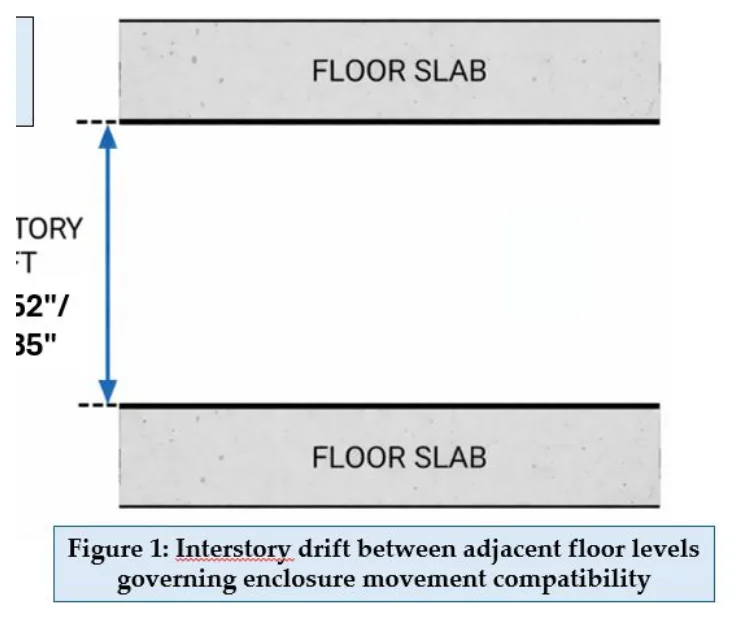
Wind strength is only half of it. The building also sways, and a façade that can't follow the frame cracks glass, tears sealant and fails at its joints. With six floors at 17′-4″ (104 ft total), she checked each system against the interstory drift it has to absorb under the 10-year MRI service wind (D + 0.7W): h/600 at the ground floor and h/400 above.

The upper floor value of 0.52 in governs. Each system takes it differently: the curtain wall at its stack joint and sliding anchors, the windows at their perimeter joints, and the rainscreen through rail and joint tolerance.

Diagram of interstory drift between two floor slabs: 0.52 inches upper floors, 0.35 inches ground floor
AP.5 · Fig. 1. Drift between adjacent slabs controls façade movement. Drift calculation →

Interstory drift to accommodate (in)

Ground floorh/600
0.35
Upper floorsh/400 · governs
0.52
00.20.40.6
SystemMovement checkStatus
Curtain wallStack joint / anchors ≈ 0.52 inFeasible with movement joint
Punched windowTwo side joints ≈ 0.26 in eachFeasible with perimeter joint
Fiber cementJoint / rail tolerance ≈ 0.26 in each sideFeasible with flexible jointing
Hand-rendered detail of the curtain wall mullion anchor: upper mullion slipped over an aluminum anchor stem, steel angle set flush with the slab edge, bolts, welds and fiber shims
S.3.2 · Fig. 3. Mullion anchor at top of slab. The slip joint is where the drift is absorbed.

Beyond strength

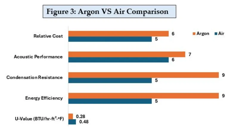
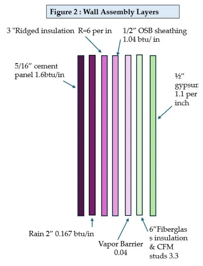
The appendix sheets carry the enclosure past structural checks. There are layer-by-layer assembly tables with weights and U-values for each system, and an argon vs. air IGU comparison on NFRC-rated properties (relative cost, acoustics, condensation resistance, energy efficiency). That comparison is why the curtain wall uses an argon cavity.

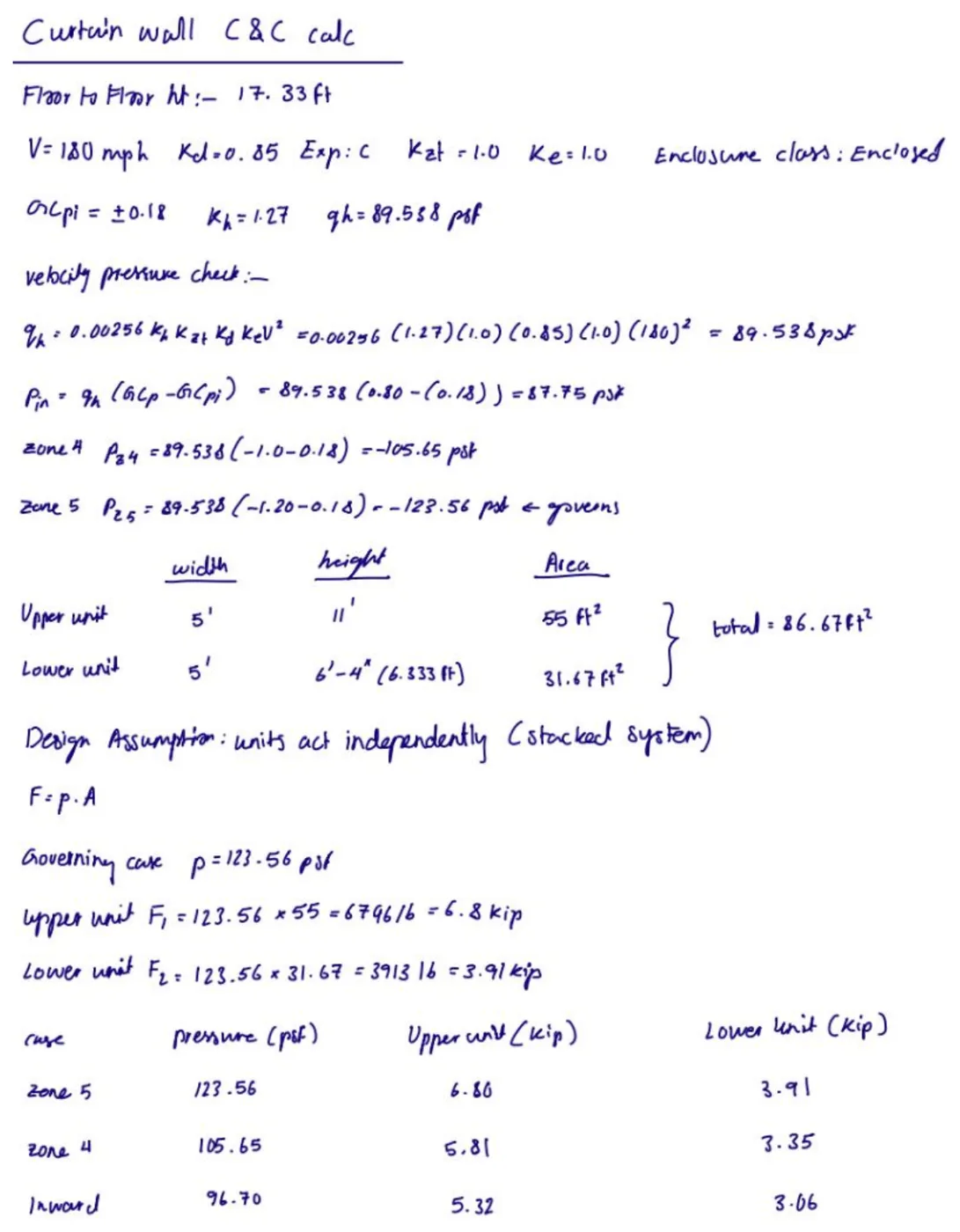
The component forces were also worked by hand. Sheet AP.6 has the handwritten C&C calculations for the curtain wall, punched window and fiber cement panels, alongside the NFRC comparison.

Assembly weights, U-values and the argon decision →

SheetS-05
Education

Penn State Architectural Engineering

The Pennsylvania State University

Bachelor of Architectural Engineering, Structural Option

Campus
University Park, PA
Graduation
December 2026 (expected)
Accreditation
ABET-accredited program
Capstone
AE 481W / AE 482, Anchor Point Engineering

The structural option covers steel, concrete and wood design, indeterminate analysis and geotechnical engineering, alongside the integrated AE core in building systems. The education page goes through every core course: what it covers, and where it shows up in the capstone.

See the full education page →
SheetS-06
Technical skills

Tools, codes & methods

Analysis & design

  • SAP2000
  • ETABS
  • RAM
  • Steel member design
  • Concrete member design
  • Timber member design
  • Wind analysis
  • Seismic analysis
  • Connection load paths

Codes & standards

  • IBC
  • ASCE 7
  • AISC 360
  • ACI 318
  • NDS
  • Florida Building Code
  • AISC Design Guide 22

Modeling & drafting

  • Revit
  • AutoCAD
  • BIM coordination
  • SolidWorks
  • SketchUp
  • Construction details

Programming & data

  • Python
  • RStudio
  • Advanced Excel
  • Microsoft 365

Project delivery

  • Schematic design
  • Assembly & detailed estimating
  • Life-cycle cost analysis
  • Project & site planning
  • Sustainable design

Visualization

  • Adobe Photoshop

● Used directly on her capstone sheets

SheetS-07
Professional involvement

In the profession

Jan 2023 – Present

Structural Engineers Association of Pennsylvania

SEAoP · Member

  • Attend technical workshops and professional development sessions on structural design practice and applying the code.
  • Talk with practicing engineers about new design standards and sustainable building strategies.
April 2025

AISC NASCC: The Steel Conference

Attendee

  • Attended sessions on steel connection design, fabrication and erection.

Open to entry-level roles

Let's talk structures.

Tamara is looking for an entry-level building structures design role, starting after she graduates in December 2026. She'd be glad to walk through the capstone sheets in detail.